
Switches and Lighting
Smart Switches vs Smart Lights: What Should Control the Circuit?
Choose between Aqara relay switches, dimmers, smart bulbs and smart luminaires while preserving physical control and a coherent power design.
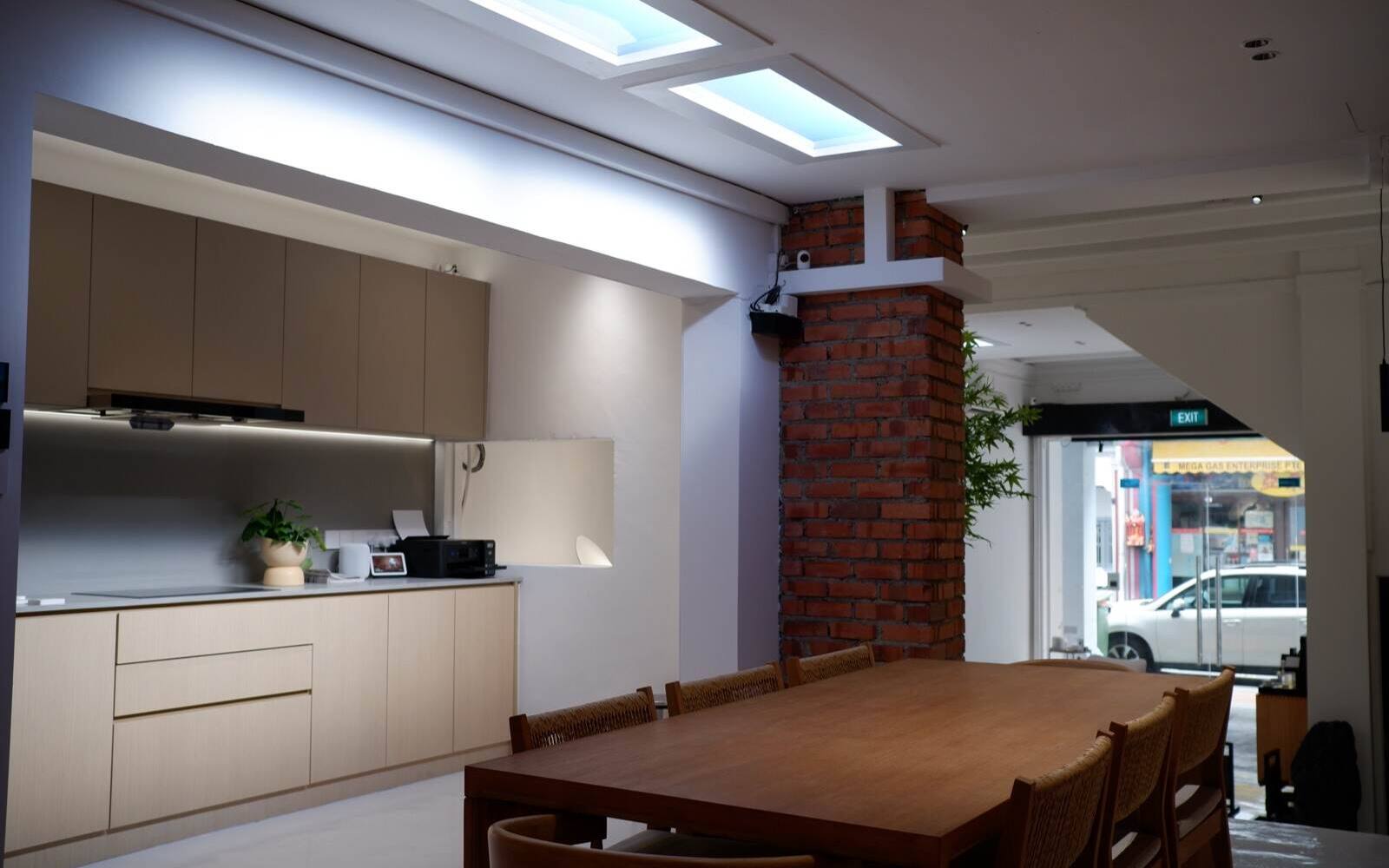
A smart wall switch turns the power to a light circuit on and off. A smart bulb or smart light fitting stays powered all the time and changes its own brightness, colour temperature or colour when it's told to. Put both on the same circuit without a plan and the light drops off the network every time someone uses the wall switch.
Which one you should use depends on what you want from the room: dependable on and off, dimming for ordinary lights, control of each light on its own, or adjustable white and coloured light.
On this page
- One circuit, one thing in charge
- Smart relay switches for ordinary on-off lights
- Dimming ordinary lights with a smart dimmer
- When smart bulbs and smart lights are the better answer
- Aqara switches with Aqara smart lights: decoupled mode and MARS-Tech
- Wiring circuits and app groups are two different things
- Keep a physical switch for guests and outages
One circuit, one thing in charge
Each light circuit needs one clear thing in charge of it. A relay switch connects and cuts the mains supply. A conventional dimmer alters the mains supply it passes on to compatible lamps or drivers. A smart light expects power all the time and changes its output when it receives a digital command.
If an ordinary wall switch cuts power to a smart bulb, the bulb can't hear the app, voice commands or automations. If a mains dimmer feeds a smart light that wasn't designed for phase-cut dimming, the light can flicker, buzz, reset or fail. They may all be called smart, but they're controlled in different ways and you can't swap one approach for another.
Shop Aqara smart switches Shop Aqara smart lighting
| Setup | Wall control | What the light can do | Power | Best for |
|---|---|---|---|---|
| Smart relay switch + conventional light | Wall switch works the relay directly | On and off | Circuit has no power when off | Simple fixed lights that work the way people expect |
| Smart dimmer + compatible conventional driver | Wall dial or buttons dim the mains supply | Brightness; colour depends on the fitting | Dimmer stays online | One dimmable circuit with drivers proven to work with it |
| Smart light on permanent power | Wireless switch, app, panel, voice or automation | Brightness, colour temperature and sometimes colour, light by light | Lights stay powered | Scenes, grouped lights and adjustable white light |
| Supported Aqara switch + Aqara smart lights | Wall switch in decoupled or MARS-Tech mode sends commands | Smart-light features plus a wall switch | Relay kept in the powered state you set | All-Aqara lighting planned and written down as one system |
Smart relay switches for ordinary on-off lights
A D1, H1, Z1 Pro or H2 relay switch can control a compatible ordinary light circuit and still work directly from the wall. The switch joins your Aqara system for schedules, automations and remote control, while the light itself needs no radio or firmware of its own.
This is the dependable choice for utility areas, bedrooms and rows of downlights that only need to go on and off. When a lamp fails, you replace it with an ordinary one, and the room still works from the wall if the internet is down. You'll need a compatible Aqara hub for the Zigbee app and automation features.
The switch still has to suit the load, your neutral wiring and the brief surge the LED drivers draw when they switch on (inrush). No-neutral switches pass a small current through the light and may not suit some low-power, dimmable or electronically controlled lights. Check the exact switch against the circuit; LED wattage alone doesn't tell you enough.
Compare Aqara D1, H1, Z1 Pro and H2
Dimming ordinary lights with a smart dimmer
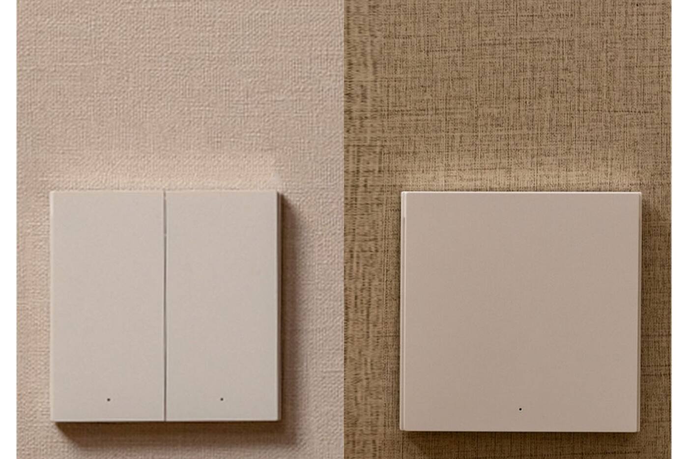
A mains dimmer makes sense when several ordinary lights should dim together and their drivers are made for that kind of dimming. The Aqara Dimmer Switch H2 EU supports compatible dimmable LED, CFL, incandescent and halogen loads within its published limits. The minimum load, and whether the lights need leading- or trailing-edge dimming, still matter.
A lamp marked ‘dimmable’ doesn't guarantee that every driver and dimmer pairing will stay steady across the whole range. Test one typical circuit at low, middle and full brightness. Set minimum and maximum levels that avoid dropouts and flicker, and test again once all the lights are connected.
A mains dimmer usually controls the whole circuit at once. It can't set colour temperature or control each downlight separately. If you want that, use smart lights on permanent power; phase-cut dimming won't get you there.
When smart bulbs and smart lights are the better answer
Aqara bulbs, downlights, track lights, strips and ceiling lights control their own brightness and, depending on the model, colour temperature or colour. Several lights on one circuit can each be set differently, or put into different groups, with no rewiring.
They're the right choice for warm evening scenes, brighter light for tasks, slow fades and control by area. The catch is that every smart light has to stay powered and connected, so the wall control should send a command instead of cutting the power.
Decide what the lights should do after a power cut, and how you'll control them by hand. You may still need an isolator for maintenance, but it shouldn't look like a switch people are meant to use every day. Note which hub or Matter controller the lights are paired with and how to add a replacement.

Aqara switches with Aqara smart lights: decoupled mode and MARS-Tech
Supported Aqara switches let you decouple a button from its relay. The button then works as a wireless control while the smart lights stay powered. Aqara's MARS-Tech goes further, coordinating the relay and the lights on specific switches with compatible Aqara lights. Requirements vary by product: you may need a neutral wire, Zigbee mode or particular Aqara light models.
Decoupling a switch doesn't automatically stop every smart bulb from losing power. Decide whether the relay is locked on, whether the button triggers a scene or controls a light directly, and what a long press or reset can do. Then check the wall switch still works when the hub, router and internet go down.
This mixed setup is worth it when you want what smart lights can do but people still expect a normal switch on the wall. For an ordinary storeroom light, it's complexity you don't need.
View Smart Wall Switch Z1 Pro View Aqara Smart Downlights T2
Wiring circuits and app groups are two different things
Electrical circuits decide which lights share power. App groups and scenes decide which smart lights respond together. A living room might have one circuit for the downlights and another for the cove lighting, while the app has TV, dining and evening groups that cut across both.
Adding extra circuits just to copy what scenes do duplicates work the app groups already handle. And a single unswitched circuit feeding every light still needs an isolator you can reach. Plan the circuits around safety and maintenance, and the app groups around how you use the room.
Label both. Write down the distribution-board circuit, wall position and app group for each light, so the app isn't the only place that tells you which breaker or relay feeds it.
Keep a physical switch for guests and outages
Every room you use often needs an obvious way to turn the light on by hand. A visitor should be able to switch on the bathroom or bedroom light without voice control or an app. That can be a relay switch, a dimmer, a wireless scene button or a decoupled smart switch, as long as it responds straight away and the same way every time.
Test each kind of failure on its own: no internet, the router restarting, the Aqara hub offline and the household platform unavailable. Local Zigbee control and automations may keep working when the internet is down, but a wireless button still needs its hub. A relay switch can still switch its circuit directly when the app features aren't available.
Use the simplest setup that gives you the lighting you want. For plain on-off rooms that's a relay switch; smart lights belong in the rooms where you'll actually use scenes and colour temperature.
Plan smart lighting for renovation Understand scenes and automations
Choose one main setup for each circuit
Ordinary lights
- Smart relay switch for on and off
- Smart dimmer for dimmable lights you've tested
- Works from the wall the way people expect
Smart lights
- Permanent power to every light
- Brightness, colour temperature or colour for each light
- A wireless or decoupled wall switch that's easy to find
Aqara switches with Aqara lights
- Only supported switch and light pairings
- A note of the relay lock, decoupled mode or MARS-Tech setting
- Local control tested during outages
Don't put a smart light behind an everyday switch that people can use to cut its power, unless the system is deliberately set up to handle that.
Official references
Product and standards information was checked against these primary sources. The article above is original Aqara Singapore editorial content.
Plan the circuit first
Pick the switch, dimmer or smart light that gives you the light you want.
Compare the switch and lighting ranges, or include your circuits and scenes in a whole-home plan.